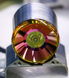
Over the last ten years, an optical design team in Finland has experimented with stretching the limits of omnidirectional live imaging, particularly for mobile phone camera add-ons with an eye toward teleconferencing applications.
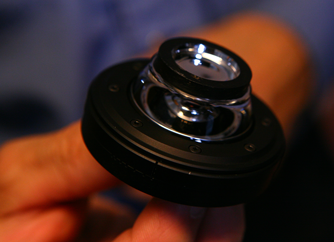
The designers say that the flexibility and sophistication of Zemax software was critical to their work, which resulted in a monolithic 360-degree lens that was not possible before with phone cameras. It offers greater resolution and a smaller footprint than the fish-eye and mirror-type designs on the market. With a 30- to 40-degree vertical field of view, the system is “the best optical design in the world for that particular use [teleconferencing]” and has a range of other potentials as well.
We spent some time with Mika Aikio, one of the lead optical designers on the project, exploring how the concept became reality. We talked about how the idea was born, what’s unusual about the lens and how it was designed, how Zemax helped, and how the technology might be used in the future.
Zemax: How did you get involved in working on an omnidirectional lens? What was the genesis of the project?
M.A.: I worked for the applied research and development organization VTT as an optical designer for 12 years, starting in VTT when I was a second-year Master of Science student at the university of Oulu. I’m educated as a physicist, with a degree from the Faculty of Sciences. My thesis was on freeform design using ray tracing, so I was definitely involved in optics right from the start of my studies.
The way VTT works is that it takes university research results and uses them to develop industrial applications in a wide variety of fields. About 2,500 people work at VTT, so there are a lot of departments and interesting projects and research going on.
I was in the Optical Instruments Center at VTT, where we did a lot of product development for companies, a real range of optical instruments—everything from lenses that went into space orbit to luminaires for underground mining. In my case I worked on projects from ultraviolet to the terahertz wavelength range, which is an unusually broad range.
It was back in 2006 that we first started to talk about add-on devices for mobile phones, and VTT decided to research the area of mobile phone add-on devices. At that point it was becoming a custom to create cameras that were add-ons to mobile phones. VTT’s spin-off company KeepLoop launched an add-on lens to turn mobile phones into microscopes, for example.
One of my senior colleagues, Jukka-Tapani Mäkinen (J-T), had the idea, when he saw a mirror put on top of a mobile phone camera, to explore and use his knowledge of plastic injection molding in creating some kind of mobile conferencing device. He saw then that mobile phones could in the future be used as conferencing platforms.
So we started to think about what kind of elements we’d want put into a mobile phone camera to create the most robust teleconferencing add-on possible, at a reasonable cost and with good image quality.
J-T oversaw the conception of the lens. I worked with a colleague, Bo Yang, who did the initial sketches, and I then took over design.

Zemax: How did you approach it, and what were the challenges?
M.A.: It took several steps because many of the assumptions inherent to lens design simply don’t apply, or have to be modified, in an omnidirectional solution. For example, there is no clear optical axis in the system, but there is clearly an axis of rotational symmetry. A lot of the analysis tools are looking for the optical axis as a reference point, but here it doesn’t exist in the way it does in a majority of objectives. So once the rays were through the initial omnidirectional lens part, the objective had to be designed to compensate for the wavefront aberrations.
Once we got the rays through in a way that we thought would give us the desired accuracy and quality, we still had a system that, as an add-on device, would have made the image too dark. The aperture ratio in the first design was too slow for a mobile phone camera, leading to unacceptable exposure times for the application. So we had to go through the design again and address one more element inside the system. Then we were able to achieve sufficient image quality that would take advantage of the camera capacity of most mobile phone systems, then or now.
But the biggest challenge was really that, since an omnidirectional lens does not have an optical axis in the traditional sense, some of the normal assumptions about lens design don’t apply, so some creative thinking and flexibility is required.
Zemax: Tell us more about this—what makes an omnidirectional lens different than other lenses and therefore a design challenge.
M.A.: Because there is a conical surface in this lens, one plane diverges, while the other one either converges or is unchanged. This creates an aberration that is essentially astigmatism, and in the case of omnidirectional lenses, all the object fields tend to suffer as a result—considerably more so than with typical lens designs. This is because the optical power of a reflective mirror tends to be more than a match for refractive lens optical powers in the visible wavelength ranges.
The biggest challenge was that, since an omnidirectional lens does not have an optical axis in the traditional sense, some of the normal assumptions about lens design don’t apply.
Additionally, since a normal optical system is rotationally symmetric, you can expect the rays to behave in a certain way, and that the focal length is well-defined with typical object-to-image plane mapping functions. We had to start by creating a mapping function for the omnidirectional objectives, as there is a central obscuration and the fish-eye objective’s f*theta law could not prescribe the mapping function in a way we would have been happy with.
Because of the introduction of the conical mirror to the optical path, when viewing the optical system from above, you’ll see rays taking paths that would be unusual in a standard lens design. Because of the conical mirror, the rays diverge along one axis but remain unaffected along the other.
Looking at the system from a cross-section plane, the rays travelling in that plane will just see a flat planar mirror and reflect accordingly. When viewed from above, the rays will see a curved mirror with a significant power, and will tend to diverge.
Complicating the issue even further, there are two mirrors, even though we’re designing a monolithic system.
To give the reader an impression of the magnitude of the effect, the astigmatism found in the non-optimized omnidirectional lens is closer to the astigmatism seen in the fast and slow axis of a laser diode.
This effect has to be compensated for by the optical designer. You have to suppress the astigmatic aberration—in other words the focal length difference—before the image is formed on the sensor. So we found that the key to designing omnidirectional lenses is suppressing the effect of the conical mirror, controlling its tendency to reflect rays along the two cross-sectional planes.
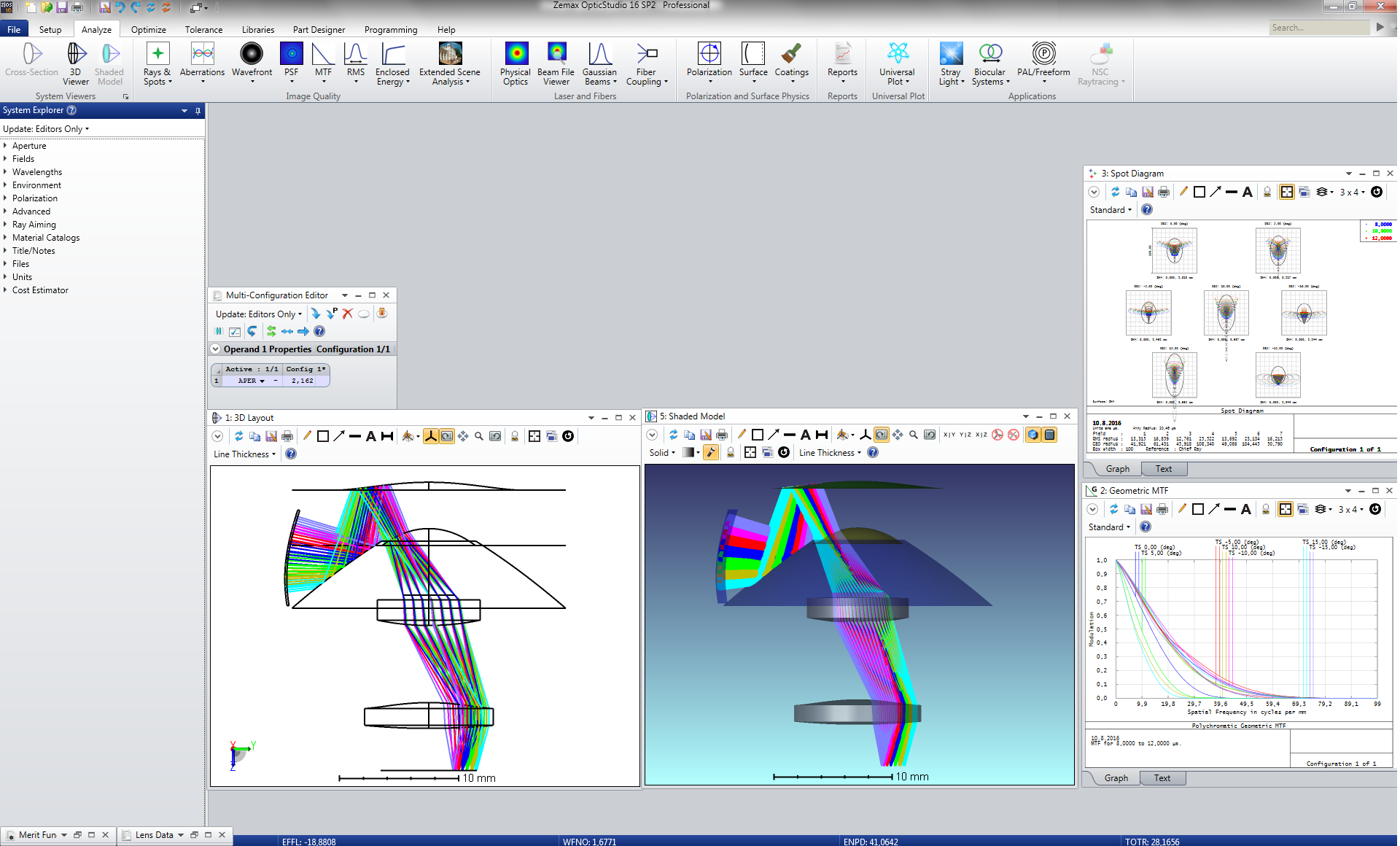
This aberration, once understood, can be suppressed with several tricks—for example, adding aspheric terms to the surfaces of the omnilens, and adding a corrective element just before the aperture stop in the objective design.
Zemax: How did Zemax software help you tackle these challenges?
Optical designers who have worked with an omnidirectional design, or who have even thought about one, assume it’s very complicated. Zemax made the design of this system remarkably easy.
M.A.: Zemax made the design of this system remarkably easy. Whenever I’ve talked about this lens to optical designers who have worked with an omnidirectional design, or who have even thought about one, they assume it’s very complicated.
It’s actually not—as long as you understand the challenges and differences in this type of lens design. Of course, discovering that was hard at first, but once we figured it out, it’s not so complicated. The software really allowed us to work out what had to be done in a relatively fast and easy manner.
One important way we used the software is related to coordinate breaks. I think what we ended up doing there is a little unusual. We often get asked regarding this design—almost with a sense of dread!—how many we had to use.
Well, in this case we only needed to use one coordinate break, and in fact the patent application has now been released for this design so it’s possible to see how it’s defined.
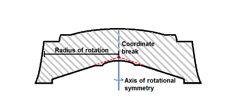 The red dot marks the position of the coordinate break with respect to the lens. Note that the position does not coincide with any of the surfaces;
instead, it is inside the lens material.
Most optical designers first think to place the coordinate break around the cylindrical surface, but actually, that’s unnecessary. The coordinate break should be located at the vertex of the conical surface (see the red dashed lines in the figure to the right).
The complicating issue is that the rays will also exit through that area of the lens (surface 4), as it’s not possible to define a reference datum to the location of the coordinate break position.
The coordinate break is essentially located at the vertex of the cone, and it rotates the cone 90 degrees, matching with the axis of symmetry. There’s no need to rotate the coordinate system any further than that.
One coordinate break makes things easy from the designer’s perspective because the less you have, the less things can go wrong in the design itself or in the merit function prescription.
Zemax: Any other ways the software particularly helped?
M.A.: I think the biggest strength of the software in the context of our omnidirectional lens is that software doesn’t place too many assumptions about the surfaces. There are four optimization options—two are local and they are quick optimizations, the damped least squares (DLS), and orthogonal descent (OD). DLS changes every parameter and updates the system after that change, while OD changes one parameter and updates the system after that and then loops over all the parameters.
In my experience, other contemporary lens design software could precalculate or try to impose assumptions regarding the position or center thicknesses of the lens. Zemax doesn’t do anything like that, which gave us freedom needed to design the lens.
The other two are global optimization methods. They are aimed at bringing the system closer to the global optimum. Global search optimization, which we use less, and Hammer optimization algorithm which we use more, are both more random search-oriented. They do not impose preferences, which made our work easier. With pre-direction from an algorithm or anything pre-programmed—like using third-order aberrations for an initial start point—the assumptions wouldn’t have been true for this geometry because the ray behavior is so different from normal objectives.
These are optimization methods that happen to use the data that the rays provide, but do not place assumptions on the system or try to precalculate anything the user doesn’t want to. Having optimization options was also great because if one algorithm got stuck, the other usually did not.
I wrote 150 rows of merit function code to keep the lens intact. That was all I needed to do to make software understand what I wanted it to do.
In my experience, other contemporary lens design software could precalculate or try to impose assumptions regarding the position or center thicknesses of the lens. Zemax doesn’t do anything like that, which gave us freedom needed to design the lens. We were able to use coordinate breaks in the creative way I described, and the optimization worked happily after the relevant data was brought to the algorithm.
Another really useful feature was the ray aiming. There’s an option in Zemax to aim rays toward the entrance pupil, and that’s definitely useful in designing an omnidirectional lens. Without that, it would have been a frustrating experience updating vignetting factors and related merit function discontinuities.
It was surprising to me that it was possible to tolerance this type of design reliably with the built-in ray-aiming algorithms. Often, getting rays through the aperture stop with omnidirectional lens designs is the first challenge, but with Zemax, ray aiming was able to keep track of the rays and ensure that all rays go through the whole aperture stop as expected.
I thought it was nothing short of amazing that ray aiming was still working when all of the surfaces were deformed at the same time. I think Zemax did a great job designing the ray-aiming algorithms.
When tolerancing, minute errors are purposefully introduced to all surfaces and the performance is evaluated afterwards. Even with these errors present, the entrance pupil was typically found by ray aiming. I thought it was nothing short of amazing that ray aiming was still working when all of the surfaces were deformed at the same time! With user guarding against excessive surface deformations, we were able to prevent the rays going outside the ray-aiming search space.
So I think Zemax did a great job designing the ray-aiming algorithms.
Since this is a non-paraxial system, the designer does have to work with the ray data itself to confirm his/her analysis or biases. We were careful to check by hand the first lens to see that rays really would be focusing. And we discovered that the software was calculating everything correctly related to the actual ray data.
So in summary I would say that the crucial features or tools that made this design possible were the coordinate breaks, ray aiming and the way optimization was implemented in Zemax.
Zemax: And the result was something unique and unprecedented?
M.A.: Yes. Omnidirectional single block lenses were unusual to begin with, and at that time it was the first omnidirectional single block lens made for a mobile phone camera. Detailed 360-degree viewing was not possible before with phone cameras.
The three previous options were fish-eye objective, mirror add-on, or the Panoramic Annular Lens (PAL). You could find mirror add-ons for iPhone. But you would have a mirror added on top of the camera, which makes the add-on quite large. And the resolving power of those designs was much lower than what we achieved. We were able to achieve 360˚ imaging with high resolving power. You can also actually find a PAL lens as a mobile phone add-on, but those are also large and usually do not provide a very high resolution, nor is its shape optimal for injection molding.
With a fish-eye objective lens, if you put a mobile phone on the table for mobile conferencing, it will compress anybody who is attending around a table because fish-eye is still mostly looking at the ceiling. The people participating are on the edges of the image and become compressed. Most of your image in the picture that you take is photographing the ceiling—obviously not ideal.
The mirror designs are typically intended for wider vertical fields of view, like 60-120 degrees. In a conferencing application, you’re then still compressing people quite a lot and do not get much detail or magnification, and the obscuration blocks the central part of the image
We designed the omnidirectional lens from the ground up for this application. We thought about the mobile phone on the table. Then we calculated the average height of the person when seated, and calculated desired field of view that way. That turned out to be 30-40 degrees depending on distance to the person. We found that one meter of distance is about typical. Because of that, it turned out we didn’t need a large vertical field of view.
That’s where we got the idea to do what we did. What we are doing is sacrificing vertical field of view for increased resolution in the image periphery. We were able to add 30 to 50 percent more pixels on to the people at the edge of the image.
We do have central obscuration in the image but, because of that, we’re able to include more details in the imaging of people, compared to a fisheye or to a mirror design.
From what I’ve seen, this is likely the smallest system that’s able to image 360 degrees and use 30-40 degrees field of view which is idea for mobile conferencing. This is the best optical design in the world for that particular application, especially from a cost and resolution perspective, as it only needs a single image sensor.
Zemax: Did you do anything else with it?
M.A.: One thing we’ve done over time is greatly reduce the form factor. By the end of 2014, we were able to decrease the volume of the lens by tenfold. Now the objective is effectively no larger than mobile phone camera objective.
We were able to reduce the complete system to roughly 13 mm in height (including the sensor), and roughly 13 mm in diameter. So far the smallest F-number I’ve explored is F/2.0 for the omnidirectional systems, which makes it compatible with current mobile phone cameras in light collection efficiency.
Recent research was aimed towards infrared wavelengths, and we also took a detour into designing laser scanner-related omnidirectional lenses. Those are different than designing conferencing omnidirectional lenses.
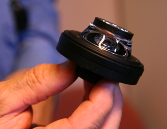
There were two EU projects related to that. One was designing miniature laser scanners that used this lens to provide beam steering, called Minifaros (under Seventh Framework Programme FP7, contract no 248123).
In laser scanners, most manufacturers would prefer not to have a rotating mirror because it’s an expensive piece. With an omnidirectional lens you can do that if you design the lens differently. We have to use a small MEMS mirror to guide the beam. The MEMS mirror will still rotate, but it is hermetically sealed into a package, and that is more reliable in the long term. We designed the omnidirectional lens for that purpose, and that was one of the steps to push this research further.
Recently we also worked on an EU project called PAN-Robots—Plug & Navigate Robots—for smart factories, a project within the Seventh Framework Programme (FP7, grant no 314193). This was a first look at the omnidirectional lens being used as a surveillance system for automated ground vehicle (AVG) forklift systems in factories. I’d like to thank European Commission for supporting this development work.
So now there are two different lens types: one with a rotating mirror that is used in laser scanners, and one without any moving parts, which is used in imaging systems such as teleconferencing objectives.
We published results in 2015 for the OSA conference (that year was "Applied Industrial Optics: Spectroscopy, Imaging and Metrology 2015” and our session was called “I Feel the Need for More Optics”) but we were working on it for 10 years before that.
Zemax: What’s happening with the lens now?
M.A.: All of this research was conducted for several different companies, which is why we have been quiet about it till now. There was a research demand from our customer side to develop and analyze this kind of omnidirectional lens for different applications over that time, and to look at the performance of this objective.
The technology was in a research and development context when I worked on it, so it’s still mostly an opportunity—but it’s highly mature at this point. The risk related to it is low and VTT has an extensive background on how to develop these lenses today.
There has been a lot of interest in the lens itself but not many products yet. We were intending to release a product, but this was first slowed and then stopped by funding issues that were not related to the technology itself.
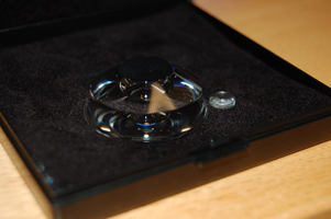
Basically, it’s a high-performing optical component looking for an industrial partner.
Zemax: Is there any application with a lens like this for the average consumer/smartphone user/amateur photographer?
M.A.: I think there could be an application for people interested in photographing a 360-degree scene, like panoramic imaging or landscape. It would be interesting to develop that product. So I’d like to see that happen and do it. It definitely would need to be affordable, and this lens is designed to be injection moldable, so that is possible. That was our target right away—we didn’t want to do something expensive.
Teleconferencing is still the intended application for the technology, though, given the vertical field of view.
You can find the patent here: Patent