The James Webb Space Telescope (sometimes called JWST or Webb) will be a large infrared telescope with a 6.5-meter primary mirror. The telescope will be launched on an Ariane 5 rocket from French Guiana in October of 2018.
JWST will be the premier observatory of the next decade, serving thousands of astronomers worldwide. The JWST can see infrared wavelengths that don’t even get to earth. That will allow astronomers—and, through images it generates, all of us—to see more, and further back, than any telescope ever could (including the famous, but smaller, Hubble Space Telescope).
The JWST will allow us to study every phase in the history of our universe, ranging from the first luminous glows after the Big Bang to the formation of solar systems capable of supporting life on earth—and the evolution of our own solar system. It will profoundly advance our understanding of astrophysics and the origins of galaxies, stars, and planetary systems.
JWST is an international collaboration between NASA, the European Space Agency (ESA), and the Canadian Space Agency (CSA). The NASA Goddard Space Flight Center is managing the development effort. The Space Telescope Science Institute will operate JWST after launch. The original design was done by Ball Aerospace in Boulder, CO.
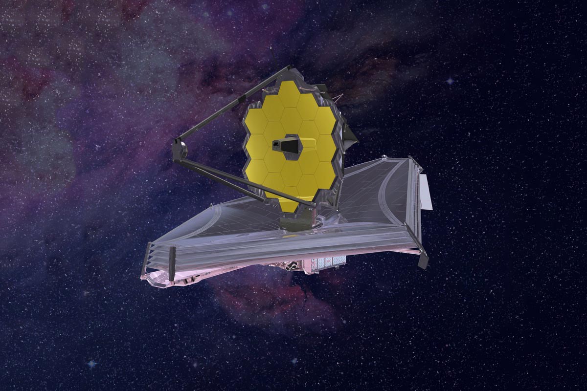
 An artist’s rendition of the James Webb Space Telescope.
(Image courtesy of NASA, from the gallery at jwst.nasa.gov)
In order to facilitate the capacities and mission of the JWST, several innovative and powerful new technologies—ranging from optics to detectors to thermal control systems—are being developed.
For example, one feature is a tennis-court-sized five-layer sunshield that attenuates heat from the sun more than a million times. The telescope’s four instruments—cameras and spectrometers—have detectors that are able to record extremely faint signals. One instrument (NIRSpec) has programmable microshutters, which enable observation of up to 100 objects simultaneously.
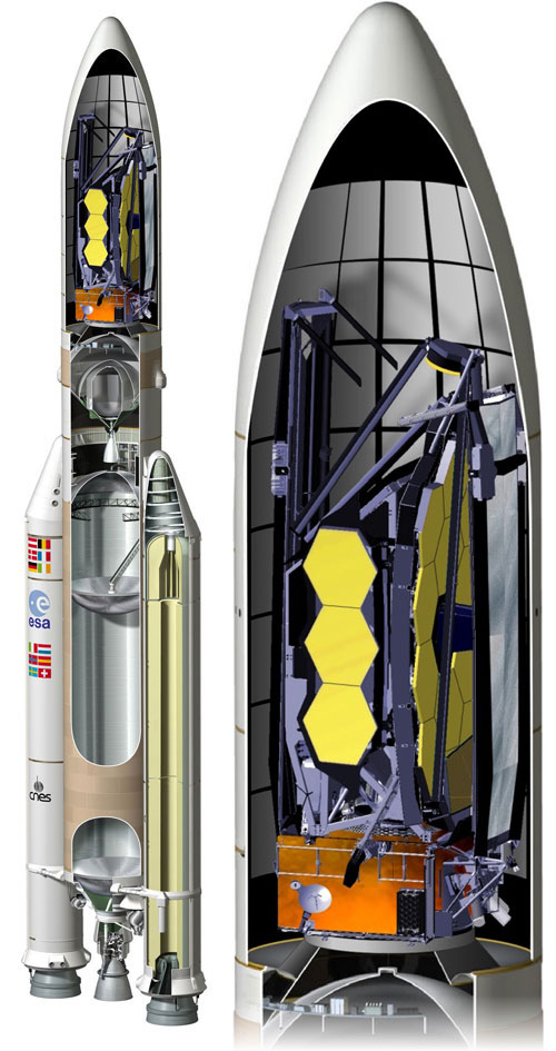
 The JWST primary mirror is folded to fit into the rocket shroud.
(Image courtesy of NASA, from the gallery at jwst.nasa.gov)
Another innovation specifically developed for JWST is a primary mirror made of 18 separate segments—constructed from ultra-lightweight beryllium—that unfold and adjust to shape after launch. This 18-segmented mirror is critical to the function and mission of the telescope. A telescope’s primary mirror is the workhorse of any telescope—it’s the mirror that gathers most of the light. The bigger the primary mirror, the more light it collects. A larger primary also produces an image with higher resolution and more detail.
Zemax is thrilled that our software was used not only to design the optics for the camera that will help align the 18-segmented mirror in space, but to custom-develop special software that will also be critical for that alignment process. (Many other software resources were also used to develop the mirror components themselves.)
The JWST and its capabilities are fascinating—and our software* being selected to ensure the extremely sensitive and delicate mirror alignment is exciting all by itself.
But the story has an extra twist for Zemax. Erin Elliott, an optical engineer who worked for five years on the primary mirror project—developing hardware and software that would allow the mirror’s 18 segments to act like single mirror once in space—came to work for Zemax in January of this year! After using Zemax 13 and Zemax for various projects, Erin now works as a Principal Optical Engineer on Zemax’s engineering team.
Erin is passionate about the JWST and the extraordinary engineering feats that will propel the project into its destiny. We had the chance to talk with her about the telescope, its 18-segment mirror, and the process of ensuring its precision alignment—so that we can see origins of life we’ve never seen before.
Zemax: You’re obviously passionate about this project. Tell us how you came to be involved with aerospace, astronomy and the JWST.
E.E.: I studied physics and Astronomy at the University of Minnesota and got my BS in physics and astrophysics. While studying astronomy, I got into telescopes and other astronomy instrumentation. I went to the University of Arizona Optical Sciences Center to study astronomy instruments and received my doctorate in optical sciences, working specifically on giant segmented telescopes, ground-based telescopes, mostly on how to model and design them.
When I finished my doctorate, I applied for a job at Ball Aerospace because I knew they had the contract to build the primary mirrors of the JWST and I wanted to work on that project. I was lucky enough to get hired there as an optical engineer, and I worked my way into the James Webb team.
The part I worked my way into was not building the primary mirror segments themselves, but the software to align them once they’re in orbit. We used Zemax extensively to construct the system that would allow that alignment to happen in space, so the 18 segments could act like a single mirror.
Having a mirror this size is critical to the mission of this telescope, and it was essential to be able to build it in segments that could be assembled later. Once we get into orbit, we have to unfold the mirror and align all the segments to behave like a single, perfectly smooth mirror. The hardware and software to perform that incredibly complex function all had to be invented from the ground up.
Zemax: So, for those of us who aren’t astronomers and engineers—why does the telescope’s primary mirror need to be in 18 segments in the first place?
E.E.: Well, we can’t launch a single mirror this big because we don’t have a rocket that big. Primary mirrors more than a few meters across don’t fit in any existing rockets. Since JWST’s primary is 6.5 meters, we have to fold it up. Once we get into orbit, we then have to unfold the mirror and align all the segments to behave like a single, perfectly smooth mirror.
The primary mirror will gather light so the telescope can gather the visual information. The JWST is an imager, among other things—it can get pictures of everything. Nebula, galaxies, whatever it looks at.
A lot of people have seen the deep field images of the universe produced by the Hubble Space Telescope. This telescope will be able to see much dimmer stars than that. The bigger this primary mirror is, the dimmer the stars we can see.
So having a mirror this size is critical to the mission of this telescope, and therefore it was essential to be able to build it in segments that could be assembled later in perfect alignment.
The hardware and software to perform that incredibly complex, key function all had to be invented from the ground up. And that’s one of the things Ball was working on when I arrived in 2003. I worked on that part of the project until 2009, when I went to the Space Telescope Institute to work on a different aspect of the telescope.
Zemax: You worked on this one part of the telescope, the segmented mirror piece, for five years?
E.E.: Yes. It’s an incredibly intensive, challenging, painstaking process. And it involved both hardware and software, and I worked on both those parts. We used Zemax on both the software and hardware parts of this project.
There is special custom software involved in aligning the mirror segments called Wavefront Sensing Control software. We also had to build optical hardware parts that would go on one of the cameras to help us take data to align the mirrors.
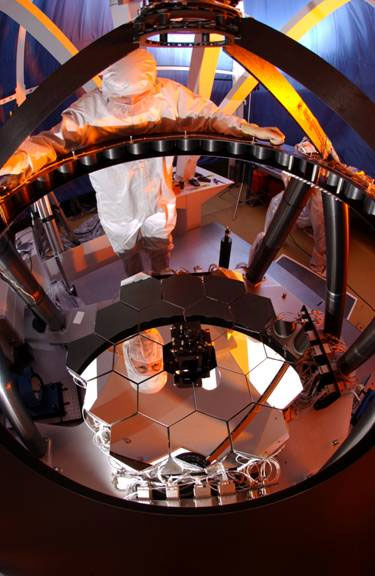
 A photograph of the JWST Testbed Telescope at Ball Aerospace.
(Image courtesy of NASA, from the gallery at jwst.nasa.gov)
There’s also another hardware element. One of the coolest parts of this project, in my opinion, is that in order to figure out how to align the mirrors, we actually built a mini telescope with 18 segments, just like the flight system, but 1/7 of the size. We called it the Testbed Telescope.
The Testbed Telescope, plus the Zemax models of the flight telescope and a software model of the Testbed Telescope, all talked to each other via the custom software to figure out how to align the segments.
It took five years to build the hardware, make sure it was all adequate for space flight, plus to create and test all the alignment software to make sure all the steps work properly. We had to be positive we wouldn’t end up down some kind of hole where, once in space, the mirrors wouldn’t align and we couldn’t get to the answer. Working on a project this big and expensive, there’s very little margin for error.
We had to be positive we wouldn’t end up down some kind of hole where, once in space, the mirrors wouldn’t align and we couldn’t get to the answer. Working on a project this big and expensive, there’s very little margin for error.
Zemax: Tell us about the hardware first. What hardware is needed to ensure the alignment of those segments? And how did Zemax help you build those optical parts?
E.E.: While no one software program was used to build the primary mirror segments themselves—that was a whole other project, which I did not work on—we did have to build hardware pieces for the system that will align the segments. The hardware is placed in the NIRCam instrument.
The JWST has several cameras on board. The NIRCam is just one. (The NIR part stands for “Near Infrared.”) NIRCam also happens to be a science instrument, which means that after it’s done aligning the primary mirror segments, it can also go “do science,” gather data and capture astronomical information.
For this camera, we built lenses and optical components to gather data and diagnose whether the segments are aligned correctly. Each mirror makes a separate image on the mirror plane. If all the segments were pointed in even slightly different directions, we’d get 18 images. But if they’re all pointing in exactly the same directions, then 18 star images all overlap to combine and make one star image.
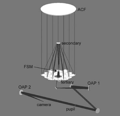
 A shaded model layout plot of the Zemax software model of the JWST Testbed Telescope.
So, we needed to design a way to be absolutely certain that the segments were all lined up in the same plane—and especially that one segment wasn’t pushed forward or back with respect to the other segments, which is an error known as “piston.” In order to figure that out, we used Dispersed Hartmann Sensors—basically like diffraction gratings, which create a spectrum instead of an image. The spectrum travels from one wavelength to the other, smearing it out in color. In this case, we can analyze those spectra to see if any of the segments had a piston error.
We also built defocus lenses. The purpose of this was to put the camera a little out of focus and use Phase Retrieval to recover details about the position of each segment. This lets us fine-tune the alignment, to give it the final tweaks.
The defocus lenses are challenging to build, because they’re mostly, but not perfectly, flat. We had to carry out detailed analysis of the defocus amounts in Zemax software, using custom macros and Zernike decompositions of the defocused wavefronts.
To model the Dispersed Hartmann Sensors, we wrote our own macros, using the ZPL Zemax programming languages, that exported and summed all the point spread functions from the different wavelengths to simulate the spectra that we needed to analyze.
While some of this could have been done with other software, Zemax has a much nicer user interface that made our job easier.
We needed a way to plan and design an unbelievable number of scenarios—things that could happen, things the mirrors might do, things that could go wrong—and try out all those scenarios virtually. Using this software, we were able to set it up so that we could flip a switch from the lab hardware to the OpticStudio™ version...and try all kinds of crazy things we wouldn’t want to try on the actual hardware. This prevented us from doing something that could actually damage the valuable lab hardware.
Using this software, we were able to set it up so that we could flip a switch from the lab hardware to the Zemax software version
Zemax: And then you also used Zemax to actually customize a software program that will “talk to” the camera and the telescope models.
E.E.: Yes. The software part of it gets even more interesting. We initially wrote all the Wavefront Sensing and Control software using IDL, or Interactive Data Language—this is software used by people who need to analyze really large images, such as in astronomy. IDL used a programming interface called Dynamic Data Exchange (DDE) to talk to Zemax13.
The thing that’s neat about it was that this software was part of a larger simulation to test what would happen in space. IDL would go to Zemax13 and get some data, then go to the Testbed Telescope and get data and bring it back. We were simulating the actual alignment in space to see if it was happening, to see if we could align the mirror.
For example, we might take the Testbed Telescope model, mess up the mirror in a strategic way, and then run our software to see if we could achieve alignment even in that situation. We could check to make sure the segments actually aligned under various conditions.
The reason Zemax was important was because we had a Testbed and we needed a way to plan and design an unbelievable number of scenarios—things that could happen, things the mirrors might do, things that could go wrong—and try out all those scenarios virtually.
There were actually two Zemax-based simulation modules as well as a real hardware version in the lab. There was a Zemax model of the Testbed telescope, Zemax simulation of the main flight system—so, two software simulations—and then the hardware version of the Testbed Telescope.
Using this software, we were able to set it up so that we could flip a switch from the lab hardware to the Zemax version of the Testbed telescope, and try all kinds of crazy things we wouldn’t want to try on the actual hardware. Then we could flip another switch and go to a different simulation version, this time representing the flight telescope.
We could say, “Okay, it seems like it worked on the Testbed model, and seemed to work on flight model, now we can go try it on the Testbed hardware.”
This prevented us from doing something that could actually damage the valuable lab hardware.
Another specific feature that was really important was the coordinate break capability. The coordinate breaks in Zemax were so flexible that we could easily model how the segments really moved...Every step had to be tested so many times in so many ways that we probably made thousands of tweaks, ran thousands of experiments trying to make it better, more accurate, faster.
Zemax: What kinds of things did you tweak or experiment with on the simulations?
E.E.: Well, as I mentioned before, I worked a lot on the Dispersed Hartman Sensors, because it turns out if a segment is too far forward or too far back it’s really hard to detect. We did a lot of simulation to figure out if we built the hardware this way or that way, can we still tell if it’s in the wrong place. There were lots of questions, like how large a piston error can we detect? How small an error? How do we calibrate the spectra?
Another specific Zemax feature that was really important to all this was the coordinate break capability. The coordinate breaks allow objects in the model to move. The coordinate breaks in Zemax13 were so flexible that we could easily model how the segments really moved. (See sidebar for more.) The segments don’t just move straight backward and forward with respect to the vertex of the primary mirror. They move in 6 degrees of freedom—piston, X and Y decenters, and XYZ tilts—all about the vertex of the individual segment.
The coordinate breaks in Zemax could correctly simulate all of these motions. The Testbed Telescope is double-pass, too, so the segment motions had to modeled correctly on both the first pass of the beam through the mirror and on the return trip. Zemax handled all that effortlessly.
Every step had to be tested so many times in so many ways that I estimate we probably made thousands of tweaks, ran thousands of experiments trying to make it better, more accurate, faster. In terms of simulating the whole process from beginning to end—getting the segments aligned into one mirror—there are maybe 20 steps to that process. And we probably simulated any one of those steps thousands of times.
What’s interesting too is that when we get to the actual launch and alignment in-flight, even with all of this technology, there will still be a human element to making the alignment happen. It turns out it was too complicated to completely automate; it’s not “point and shoot.” The software will talk to an engineer on Earth, sending data and images back for a user to check and say go ahead to the next step. Someone will be watching the steps happen and gatekeeping each next step to be sure it’s going in the right direction.
Zemax: How big was the team you worked with on this project?
E.E.: Just on the software part, in wavefront sensing control, about seven people. On the hardware part, including components for the NIRCam, we had about 40 people working at various stages of the process.
There were so many roles needed for this process, even besides optical engineers—we also had systems engineers responsible for looking at the system as a whole, fabricators who built the optical parts, technicians who handled all the hardware, mechanical engineers who designed mounts, production engineers who make sure things go from a to b to c, and materials engineers checking to make sure all materials can survive the rigors and harsh environment of space. Among others!
Zemax: Where is the project now?
E.E.: The flight software was delivered, and the primary segments that Ball built were delivered to Goddard Space Flight Center, who is in charge of putting the mirror segments onto backplane, or supporting frame. They’re in the stage now where they are close to taking it to Houston to test the whole assembly (the primary mirrors, backplanes, and the package that carries all the cameras and instruments) in a giant cryogenic vacuum chamber.
Incidentally, this is the same chamber that was used to test the moon lander, back in the Apollo days.
Launch is scheduled for 2018. So that’s exciting!
Zemax: Why did you come to work for Zemax?
E.E.: Well, in 2013, the launch got delayed until 2018, and I had spent a decade on it. After five years doing the work I just described, I spent another five years following the project from Ball to the next step. It was time for me to do something new.
I began looking at professional organization websites, and Zemax had a job posted and I thought it would be incredibly fun to work on the software side. One thing that’s fun about it for me is you get to do a lot of theory work. I had a suspicion I would like working with optical theory—and I do!
I applied and I got the job. I actually did contract work for Zemax for a while so that we could try each other out. That went very well—it’s really fun working for a smaller, dynamic company—so I came on full-time in January.
My role is Principal Optical Engineer on the engineering team, and I get to do all kinds of things—develop and test new features for the software, help customers who are stuck with engineering problems, teach training courses, publish articles in the Knowledge Base on interesting things you can do with the software. It was amazing to do something so powerful using Zemax software, and it’s nice to pass that knowledge and experience on to others.
As an ex-hardware person, I’m also thrilled that Zemax is developing LensMechanix. The ability to trace rays inside SolidWorks will help prevent errors in the many, many handoffs between optical and mechanical engineers.